
Views: 0 Author: Site Editor Publish Time: 2026-08-09 Origin: Site
Plant operators and pipeline engineers constantly face severe isolation challenges in heavy industrial environments. They require secure, leak-free shutoffs to maintain process safety. This capability proves absolutely crucial in large-diameter piping, high-vibration systems, or terminal dead-end services. Standard wafer or lug valves often fail to meet strict safety tolerances under these aggressive conditions. They lack the massive structural rigidity required to withstand shifting pipe loads.
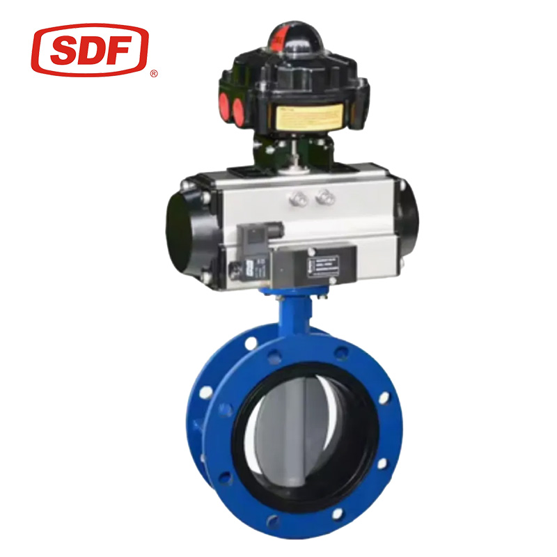
To solve these structural stability challenges, engineers turn to the flanged butterfly valve. It bolts directly to the pipe flanges on both sides. This solid mechanical connection distributes piping stress evenly across the entire joint. You successfully avoid disastrous leaks and valve body distortion under heavy mechanical loads.
This guide provides a clear, engineering-aligned breakdown of valve classifications. We will carefully examine offset geometry and body design variations. Understanding these distinct technical differences streamlines your entire procurement process. You will ensure total system compatibility, maximize operational safety, and guarantee long-term pipeline reliability.
Flanged butterfly valves are categorized primarily by disc offset (concentric, double-offset, triple-offset) and body casting (U-type vs. double-flanged).
Double and triple-offset flanged valves are essential for high-pressure, high-temperature, and severe-service environments, whereas concentric types suit standard water and low-pressure utility lines.
Unlike wafer types, flanged designs allow for true bidirectional dead-end service without downstream flange support.
Proper selection requires aligning ASME/EN flange standards, pressure-temperature (P-T) ratings, and seat materials with exact process conditions.
Understanding exactly when to choose a Flanged Butterfly Valve over simpler alternatives determines the ultimate safety of your piping network. The decision rests heavily on fundamental structural mechanics and the physical demands of your specific process fluid.
Standard clamped wafer designs rely entirely on friction and bolt tension applied between two adjoining pipes. This clamped setup poses severe failure risks in large-diameter lines, typically those exceeding 12 inches. Immense fluid volume and heavy line pressure create massive moment forces on the valve body. Flanged connections solve this issue by distributing mechanical loads effectively. They bolt independently to the mating flange. This robust anchoring prevents valve body distortion during heavy fluid surges or sudden water hammer events. Your pipeline remains secure even under severe mechanical strain.
Pipeline maintenance routines frequently require engineers to remove downstream pipe spools while keeping the upstream system fully pressurized. Double-flanged valves isolate flow safely during this dangerous process. Because they bolt directly and securely to the upstream flange, they effectively hold back the full line pressure. Wafer valves would simply slip out and fail immediately if downstream support vanished. The flanged body guarantees a secure perimeter, protecting maintenance personnel working on the open downstream end.
Industrial systems often suffer from heavy pump vibration or intense thermal cycling. Continuous vibration easily destroys weaker clamped seals. Thermal cycling expands and contracts adjacent piping, causing wafer gaskets to blow out or leak over time. Engineers mandate rigid flanged connections in these volatile environments. The massive bolted flanges lock the valve body completely in place. This solid integration dampens harmonic vibrations. You maintain a steady, secure seal regardless of external system shaking or temperature swings.
The physical geometry of the disc and stem directly dictates the performance limits of the valve. Engineers categorize these mechanisms by how the stem aligns with the center of the pipe.
In this traditional design concept, the stem centers precisely inside the disc. The disc also centers perfectly inside the valve bore. This geometry relies entirely on rubber or elastomer seat interference to seal the flow. The disc constantly rubs against the soft seat during operation.
We consider this a highly cost-effective isolation method. Facilities use concentric models frequently in cooling water loops, HVAC systems, and low-pressure utility fluid transport. However, critical limitations exist. The constant rubbing creates high friction wear on the rubber seat. They fail rapidly if exposed to abrasive media, chemical solvents, or high temperatures.
Engineers improved the baseline design by moving the stem away from the disc center and the pipe centerline. This specific dual offset creates a unique cam action inside the body. The disc lifts off the seat quickly upon the first few degrees of opening.
This cam action drastically reduces seat friction. You gain a substantially longer cycle life compared to concentric models. Manufacturers typically outfit these valves with PTFE or reinforced polymer seats. They excel as high-performance isolators. We specify them routinely for chemical processing, saturated steam applications, and medium-pressure industrial environments.
Extreme environments demand extreme geometry. This severe-service design adds a third conical offset to the seating angle. The resulting mechanical action creates a completely frictionless, metal-to-metal seal. The disc only touches the internal seat at the exact microsecond of closure.
You achieve remarkable zero-leakage performance based on strict API 598 standards. These heavy-duty valves survive extreme process temperatures exceeding 1000°F. The lack of soft elastomers means they handle aggressive fluids effortlessly. High-pressure oil and gas refineries and power generation plants rely exclusively on this geometry.
Offset Type | Primary Seat Material | Friction Level | Best Application Environment |
|---|---|---|---|
Concentric (Zero Offset) | Elastomer (EPDM, NBR) | High (Constant rubbing) | Water, HVAC, Low-pressure utilities |
Double Offset | Polymer (PTFE, RTFE) | Medium (Cam action lift) | Chemicals, Steam, Medium-pressure |
Triple Offset | Solid / Laminated Metal | Zero (Frictionless seating) | Extreme temps, Oil & Gas, High-pressure |
Valve body castings determine your installation footprint, overall weight, and specific mounting capabilities. You must match the body style to your pipeline's physical constraints.
This design features two entirely distinct flanges cast directly into the body. You get flat-faced or raised-face connection points on both the upstream and downstream sides. It represents the heaviest and most robust construction available in the valve market.
Industries deploy them standardly in heavy industrial processing. They dominate marine pipelines, offshore platforms, and massive municipal waterworks. When you deal with massive pipe diameters and require maximum stability, the standard double-flanged body provides unparalleled security. The extra weight is a worthwhile trade-off for the increased structural integrity.
U-section bodies offer a different geometric approach. They feature a much shorter face-to-face dimension. The external body profile resembles a distinct "U" shape. The flanges are fully tapped for bolting, but they share a closer, consolidated central web.
You effectively balance the secure bolting nature of a flanged valve with a noticeably reduced physical footprint. They weigh slightly less than their standard double-flanged counterparts. Engineers frequently specify U-section valves in tight piping galleries, skid-mounted equipment, or cramped shipboard applications where installation space remains highly restricted.
Specifying the perfect Flanged Butterfly Valve requires strict adherence to global engineering standards. You must evaluate dimensions, bolting patterns, and chemical compatibility meticulously.
You must navigate industry dimensional standards carefully to ensure the valve fits your existing pipe gap. API 609 governs many industrial butterfly valves. Category A covers concentric designs, while Category B governs robust offset models. AWWA C504 handles strict municipal waterworks requirements. ISO and EN standards ensure exact fitment for global and European pipelines. Always verify the manufacturer's published face-to-face dimensions against your pipeline drawings before approving any installation.
Your valve flanges must match your pipeline flanges perfectly. ASME B16.5 outlines precise dimensions for Class 150, 300, and 600 systems in North America. European systems utilize PN10, PN16, or PN40 metric designations. Mismatched bolt-hole patterns lead directly to disastrous installation failures. You cannot drill out holes or force an incorrect flange to fit. Always double-check the bolt circle diameter and hole count during the procurement phase.
We must match internal sealing materials to the process fluid's exact chemical makeup and temperature profile.
Elastomers (EPDM/NBR): These serve as the standard choice for concentric models. EPDM handles water and mild chemicals well. NBR works great for oils. However, strict temperature limits apply. They typically degrade above 250°F.
Plastics (PTFE/RTFE): Engineers choose these for superior chemical resistance. Used widely in double-offset models, PTFE resists harsh acids and corrosive solvents. They handle moderate heat, usually up to 400°F.
Laminated or Solid Metal: These are absolutely critical for triple-offset applications. They provide extreme heat resistance and meet strict API 607 fire-safe requirements. Metal seats handle abrasive particulates without suffering immediate severe damage.
Even the most perfectly engineered valve will fail if maintenance teams install it improperly. Understanding field realities prevents premature system downtime.
Improper bolting introduces severe operational risks. Uneven cross-bolting can crush flange gaskets unevenly. More importantly, uneven torque distorts the internal valve seat. This distortion causes the internal disc to bind heavily during operation. It might even prevent the valve from closing entirely.
Mechanics must always use a calibrated torque wrench. You should follow a strict star-pattern bolting sequence. Apply torque in incremental stages rather than tightening one bolt fully before moving to the next. Proper alignment ensures the internal bore remains perfectly cylindrical.
You must watch out for internal pipe clearance closely. Unlike gate valves, butterfly discs swing open directly into the interior pipeline. Heavy-wall piping or schedule 80 pipes possess much thicker walls. Consequently, their internal diameter shrinks significantly.
The valve disc might strike the inner pipe wall upon opening. This collision damages the disc edge and destroys the seating surface. Always check the chordal dimension of the valve disc against your pipe's exact inside diameter. Beveling or chamfering the inner pipe edges often solves minor interference issues safely.
Selecting the proper heavy-duty isolation equipment does not have to be an overwhelming challenge. We can summarize the entire engineering logic quite easily. Your final choice hinges directly on pressure and temperature demands. These specific operational factors dictate whether you need a concentric, double, or triple offset mechanism. Meanwhile, your pipeline's structural stability and dead-end maintenance requirements dictate the flanged body type. Double-flanged bodies offer maximum anchor strength, while U-section bodies save crucial space.
Before you finalize any pipeline upgrade or purchase order, gather your empirical data. Compile your system's exact pressure-temperature ratings. Document all media characteristics, paying special attention to corrosiveness and abrasive particulate count. Confirm your exact flange class specifications. Once you organize these parameters, consult directly with an established valve manufacturer. They will utilize this data to finalize the sizing and guarantee your equipment performs safely for decades.
A: Yes, you can use them for flow throttling. Double and triple offset designs perform excellently within the 30° to 70° open range. However, their primary engineering use remains strict on/off isolation. Prolonged throttling near the closed position can cause severe seat erosion over time.
A: Lug valves have threaded metal inserts along their perimeter. You bolt them independently from both sides using short bolts. Flanged valves feature full, solid cast flanges that match the pipe flange directly. This offers much higher structural stability and vibration resistance for large diameter piping.
A: Concentric and double offset designs are generally bidirectional. They seal effectively regardless of flow direction. However, triple offset valves often feature a preferred sealing direction to achieve optimal zero-leakage performance under high pressure. Always check the manufacturer's flow arrow before you bolt them into the line.


